|
Electrodynamic Tether 02 |
|||||||||||||||||||||||||||||||||||||||||||||||||||||||||||||||||||||||||||||||||||||||||||||||||||||||||||||||||||||||||||||||||||||||||||||||||||||||||||||||||||||||||||||||||||||||||||||||||||||||||||||||||||||||||||||||||||||||||||||||||||||||||||||||||||||||||||||||
|
..
NASA STS 75 Mission Launch Date: February 22, 1996, 20:18:00 UTC
The space tether experiment, a joint venture of the US and Italy, called for a scientific payload--a large, spherical satellite--to be deployed from the US space shuttle at the end of a conducting cable (tether) 20 km (12.5 miles) long. The idea was to let the shuttle drag the tether across the Earth's magnetic field, producing one part of a dynamo circuit. The return current, from the shuttle to the payload, would flow in the Earth's ionosphere, which also conducted electricity, even though not as well as the wire. One purpose of such a set-up might be to produce electric power, generating current to run equipment aboard the space shuttle. That electric comes at a price: it is taken away from the motion energy ("kinetic energy") of the shuttle, since the magnetic force on the tether opposes the motion and slows it down. In principle, it should also be possible to reverse this process: a future space station could use solar cells to produce an electric current, which would be pumped into the tether in the opposite direction, so that the magnetic force would boost the orbital motion and would raise the orbit to a higher altitude. The first attempt at the tether experiment ended prematurely when problems arose with the deploying mechanism, but the one on February 25, 1996, began as planned, unrolling mile after mile of tether while the observed dynamo current grew at the predicted rate. The deployment was almost complete when the unexpected happened: the tether suddenly broke and its end whipped away into space in great wavy wiggles. The satellite payload at the far end of the tether remained linked by radio and was tracked for a while, but the tether experiment itself was over. It took a considerable amount of detective work to figure out what had happened. Back on Earth the frayed end of the tether aboard the space shuttle was examined, and pieces of the cable were tested in a vacuum chamber. The nature of the break suggested it was not caused by excessive tension, but rather that an electric current had melted the tether. The electric conductor of the tether was a copper braid wound around a nylon string. It was encased in teflon-like insulation, with an outer cover of kevlar, a tough plastic also used in bullet-proof vests, all this inside a nylon sheath. The culprit turned out to be the innermost core, made of a porous material which, during its manufacture, trapped many bubbles of air, at atmospheric pressure. Later vacuum-chamber experiments suggested that the unwinding of the reel uncovered pinholes in the insulation. That in itself would not have caused a major problem, because the ionosphere around the tether, under normal circumstance, was too rarefied to divert much of the current. However, the air trapped in the insulation changed that. As it bubbled out of the pinholes, the high voltage ("electric pressure") of the nearby tether, about 3500 volts, converted it into a plasma (in a way similar to the ignition of a fluorescent tube), a relatively dense one and therefore a much better conductor of electricity. The instruments aboard the tether satelite showed that this plasma diverted through the pinhole about 1 ampere, a current comparable to that of a 100-watt bulb (but at 3500 volts!), to the metal of the shuttle and from there to the ionospheric return circuit. That current was enough to melt the cable. As the broken end whipped away from the shuttle, the plasma established electric contact with the ionosphere directly. The satellite on the distant end monitored the current: after about half a minute it stopped, then it reignited and flowed again for about another half minute, stopping for good when (presumably) all the trapped air was gone. Because of the unexpected break, the tether experiment at the time was widely viewed by the press as an expensive failure. True, the planned operation at full deployment, for several hours, could not take place, nor could the tether and its satellite be retrieved, which was to have demonstrated the feasibility of deployable tethers. However, many of the scientific experiments had already begun during deployment and yielded good data. And the break itself, though unfortunate, added an unscheduled experiment to the mission, one which highlighted the risks and complexities of operating scientific equipment in space. SOURCE: NASA |
|||||||||||||||||||||||||||||||||||||||||||||||||||||||||||||||||||||||||||||||||||||||||||||||||||||||||||||||||||||||||||||||||||||||||||||||||||||||||||||||||||||||||||||||||||||||||||||||||||||||||||||||||||||||||||||||||||||||||||||||||||||||||||||||||||||||||||||||
|
The US NAVY Space Command |
|||||||||||||||||||||||||||||||||||||||||||||||||||||||||||||||||||||||||||||||||||||||||||||||||||||||||||||||||||||||||||||||||||||||||||||||||||||||||||||||||||||||||||||||||||||||||||||||||||||||||||||||||||||||||||||||||||||||||||||||||||||||||||||||||||||||||||||||
|
Small Tether Satellite Deployed by NRL 20 June 1996
(Washington, DC) -- The Naval Research Laboratory's
(NRL's) Naval Center for Space Technology has designed, built and deployed
a small satellite to research the gravity-gradient dynamics and survivability
of a tethered system in space, known as the Tether
Physics and Survivability (TiPS) experiment.
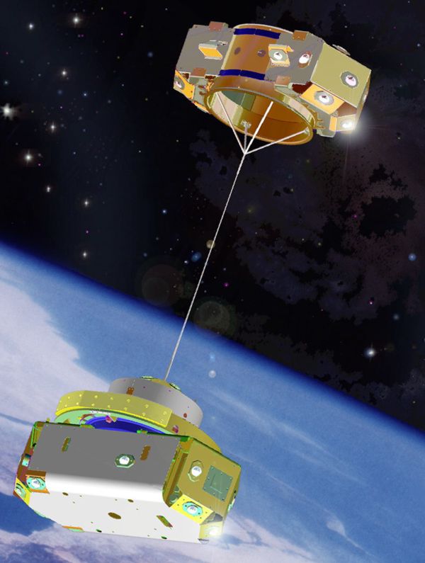
The TiPS satellite was deployed today into a circular orbit, at an altitude of 1022 km (552 nmi) and inclination of 63.4 degrees. A deployment sequence jettisoned the TiPS satellite from a host vehicle and then separated its two end masses from each other. When fully deployed, the 53.5 kg (118lb.) tethered system consisting of two small end-masses is connected by a 4 km (2.5 miles) nonconductive braided tether. NRL, NASA, and an international network of Satellite Laser Ranging (SLR) stations are tracking the position of each end-mass to study the dynamics and survivability of tethered systems. Telemetry generated during the separation of the two end-masses was received by the United States Air Force (USAF). The National Reconnaissance Office (NRO) is a sponsor of the TiPs program. Research and funding for this low-cost, passive experiment began in 1995. The NRO helped fund this project to increase understanding of gravity gradient tether dynamics for space operations. In addition, NRO engineers hope the research will assist the scientific community in evaluating survivability of future tethered vehicles in low-earth orbit. Mr. Robert Towsley, TiPS Systems Engineer at NRL, explains "Tethered systems are a new and relatively untested space technology. The TiPS spacecraft is designed to characterize tether dynamics and survivability in the space environment. Specific dynamics issues of tethered systems include libration amplitudes and stability, while tether issues include internal damping and flexibility." Dr. Shannon Coffey, Mission Operations Manager of NRL's TiPS, adds "From a survivability aspect, TiPS' tether is susceptible to space debris damage. The tether, roughly 2 mm in diameter, can be severed by a particle as small as 1mm travelling at a relative velocity of 14km/s (31,318 mph)." Mr. William Purdy, NRL's TiPS Program Manager says, "The TiPS endmasses are similar in size and weight, which dictates that both will undergo significant dynamic motion with respect to the center of mass of the system. The heaviest end mass, affectionately dubbed "Ralph," weighs 37.7 kg (83.2 lb.). Ralph contains all of the electronic components, which include the telemetry system, turncount recorder, and temperature sensors. The telemetry system, supplied by NASA, is powered by a nonrechargeable battery, which operated for the first eight hours of the satellite's life. The lighter end-mass dubbed "Norton" weighs 10.3 kg (22.8 lb.). The tether weighs 5.5 kg (12.0 lb.), and was coiled on a spool inside Ralph, much like a spinning reel." Ralph and Norton separated at a relative velocity of approximately 5.1 m/s (16.7 ft/s). The passive deployment scheme utilized a small Marman clamp and ten spring-loaded cartridges. The initial separation energy was designed to deploy about 2 km of the tether, at which time gravity-gradient forces assisted to unwind the remainder. The TiPS orientation is controlled by gravity gradient forces. The TiPS satellite orbits the Earth with a nominal vertical orientation, Ralph being closest to the earth. About this nominal orientation, the tethered system undergoes libration, a pendulum-like motion, about the center of mass. A globally distributed SLR network, including NASA, DoD, and cooperating international stations, are tracking the TiPS satellite. These SLR stations provide very accurate, submeter-resolution, range data for Ralph and Norton. The SLR information is being used to determine the orbit and attitude of the tethered system. Ms. Amey Peltzer, NRL's TiPS SLR Mission Specialist reports, "This is the first time SLR data has been converted into attitude and orbit knowledge, to validate analytical models and simulations of a tethered system." Retroreflectors are mounted on the exterior surfaces of both Ralph and Norton, for long-term passive monitoring of the tethered system. End-mass discrimination is accomplished by coating the retroreflectors of Ralph to reflect only one of the two transmitted laser wavelengths. The uncoated retroreflectors on Norton reflect both transmitted wavelengths. And Mr. Towsley adds, "TiPS is a low-budget, quick-reaction experiment. To date, mathematical models have been developed to predict the motion and survivability of tethers in space, but little long-duration on-orbit data have been obtained. The data from TiPS will be used to verify and improve understanding of the physics of tethered systems in space as well as the mathematical models." The Naval Research Laboratory is the Department of the Navy's corporate laboratory. NRL conducts a broad program of scientific research, technology and advanced development. The Laboratory, with a total complement of nearly 4,000 personnel, is located in southwest Washington, DC, with other major sites at the Stennis Space Center, MS; and Monterey, CA. SOURCE: NRO Press Release |
|||||||||||||||||||||||||||||||||||||||||||||||||||||||||||||||||||||||||||||||||||||||||||||||||||||||||||||||||||||||||||||||||||||||||||||||||||||||||||||||||||||||||||||||||||||||||||||||||||||||||||||||||||||||||||||||||||||||||||||||||||||||||||||||||||||||||||||||
|
The TiPS Mission ..   |
|||||||||||||||||||||||||||||||||||||||||||||||||||||||||||||||||||||||||||||||||||||||||||||||||||||||||||||||||||||||||||||||||||||||||||||||||||||||||||||||||||||||||||||||||||||||||||||||||||||||||||||||||||||||||||||||||||||||||||||||||||||||||||||||||||||||||||||||
| The TiPS Mission
The Naval Center for Space Technology recently built and launched a Tethered Satellite called TiPS. The TiPS satellite is a tether physics experiment consisting of two end masses connected by a 4 km non-conducting tether. The satellite was deployed on 20 June 1996 at an altitude of 1,022 kilometers (552 nautical miles). This experiment is designed to increase knowledge about gravity-gradient tether dynamics and the survivability of tethers in space. (Tethers can be severed by space debris.) The National Reconnaissance Office (NRO) is a sponsor of the TiPS program. While tethers have been theoretically studied as a means for satellite stabilization, propulsion, and electricity generation for some time, TiPS is among the first successful tether deployments in space and is the first experiment designed for long duration. This site provides access to numerous technical documents explaining TiPS predictions and analysis, and images of the satellite during design, deployment, and operations. The scientific community can access TiPS observation data through this web site. A TiPS public relations video is available from NRL
Public Affairs, (202) 767-2541.
SOURCE: Projects NRL Navy |
|||||||||||||||||||||||||||||||||||||||||||||||||||||||||||||||||||||||||||||||||||||||||||||||||||||||||||||||||||||||||||||||||||||||||||||||||||||||||||||||||||||||||||||||||||||||||||||||||||||||||||||||||||||||||||||||||||||||||||||||||||||||||||||||||||||||||||||||
.... .... |
|||||||||||||||||||||||||||||||||||||||||||||||||||||||||||||||||||||||||||||||||||||||||||||||||||||||||||||||||||||||||||||||||||||||||||||||||||||||||||||||||||||||||||||||||||||||||||||||||||||||||||||||||||||||||||||||||||||||||||||||||||||||||||||||||||||||||||||||
..
|
|||||||||||||||||||||||||||||||||||||||||||||||||||||||||||||||||||||||||||||||||||||||||||||||||||||||||||||||||||||||||||||||||||||||||||||||||||||||||||||||||||||||||||||||||||||||||||||||||||||||||||||||||||||||||||||||||||||||||||||||||||||||||||||||||||||||||||||||
|
TiPS Deployment Pictoral History ..
The images were gathered using a 1.5 meter telescope at the Air Force's Starfire Optical Range at the Air Force Research Laboratory’s Directed Energy Directorate, Kirtland AFB. The images were gathered starting one minute after the separation of the two end bodies on day 172, 10:34 GMT. These observations corroborated the deployment length vs. time measurements made on board TiPS.
..
..
..
..
..
..
..
..
..
..
|
|||||||||||||||||||||||||||||||||||||||||||||||||||||||||||||||||||||||||||||||||||||||||||||||||||||||||||||||||||||||||||||||||||||||||||||||||||||||||||||||||||||||||||||||||||||||||||||||||||||||||||||||||||||||||||||||||||||||||||||||||||||||||||||||||||||||||||||||
|
..
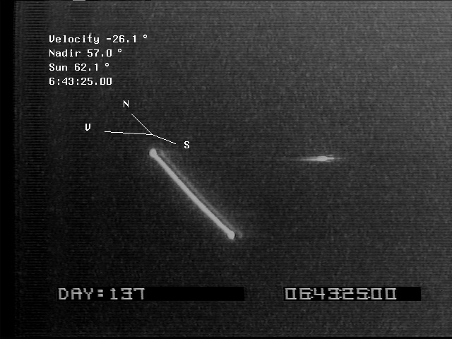
A number of processed images of TiPS are available below. These were all taken by the Maui Space Surveillance System's Air Force Maui Optical Station (AMOS) and processed by both AMOS and NRL. In these images the projections of the Velocity, Nadir and Sun vectors onto the image plane are displayed. Also, the angle between the image plane and each of these vectors is displayed in the upper left. A positive angle indicates that the vector is towards the observer. |
|||||||||||||||||||||||||||||||||||||||||||||||||||||||||||||||||||||||||||||||||||||||||||||||||||||||||||||||||||||||||||||||||||||||||||||||||||||||||||||||||||||||||||||||||||||||||||||||||||||||||||||||||||||||||||||||||||||||||||||||||||||||||||||||||||||||||||||||
|
.. Apolloisgo
TiPS was launched in 1996 by the US Naval Research Laboratory. A four-kilometre long tether connected two satellites named Ralph and Norton. The two satellites together had a mass just under 50 kilograms. Tethered satellites show promise in helping with orbital maneuvering, power generation and artificial gravity tests. This experiment was concluded in late 2006 when the tether presumably broke. I captured this video in the summer of 2004 with an Astrovid StellaCam EX, Celestron 8-inch NexStar GPS telescope with f/2 Fastar optics, NexRemote and SatelliteTracker software and a soundtrack from the shortwave time signal WWV from an observing site inside Toronto. The field of view here is about 40' x 50', slightly larger than the Full Moon. |
|||||||||||||||||||||||||||||||||||||||||||||||||||||||||||||||||||||||||||||||||||||||||||||||||||||||||||||||||||||||||||||||||||||||||||||||||||||||||||||||||||||||||||||||||||||||||||||||||||||||||||||||||||||||||||||||||||||||||||||||||||||||||||||||||||||||||||||||
|
TiPS Dynamics from Optical Data ..
The following charts show a summary of the results we've been able to get from TiPS optical data so far. The optical data is videotaped passes from telescopes around the world. By comparing the image seen on the videotape and a computer simulation of the pass, and by taking data points at multiple times during a pass, we are able to determine point or amplitude solutions. Point solutions are simply the in-plane or out-of-plane libration of angles at a specific instance in time. If enough point solutions are available in a given pass, the libration amplitude may be determined. This data has compared very well with the solutions obtained from SLR observations. There have been a number of blind comparisons made with SLR predictions, the in-plane positions generally have agreed to within a degree.
..
.. Details of data points and error bars:
TiPS SLR Observation Data This is the list of passes that
have been acquired by either optical or SLR means.
TiPS Technical Specifications TiPS Orbit and Tether Dynamics Data
A number of images of TiPS are available below. These range from photographs of the satellite taken at NRL during the summer of 1995 to recent observations of TiPS in space. We have video from most of the TiPS SLR passes. Please email us if you are interested in researching this optical data further.
|
|||||||||||||||||||||||||||||||||||||||||||||||||||||||||||||||||||||||||||||||||||||||||||||||||||||||||||||||||||||||||||||||||||||||||||||||||||||||||||||||||||||||||||||||||||||||||||||||||||||||||||||||||||||||||||||||||||||||||||||||||||||||||||||||||||||||||||||||
|
TiPS Libration Amplitudes Dampen with Time ..
The preceding chart the damping of the libration amplitudes over the first year of the TiPS experiment. The solid points are the solutions determined from the SLR and radar observation using GEODYN. The hollow points were determined using optical imagery. Although solutions for the tether libration were relatively difficult to obtain, those found to date clearly show a major reduction in the motion of the system. Tether dynamicists believe that this damping is due to internal friction within the tether itself, as opposed to environmental effects such as drag. The details of the solutions given are publicly available by contacting the author. The errors associated with them vary with the magnitude of the tether motion. However, in most cases they are thought to be correct to within a few degrees. |
|||||||||||||||||||||||||||||||||||||||||||||||||||||||||||||||||||||||||||||||||||||||||||||||||||||||||||||||||||||||||||||||||||||||||||||||||||||||||||||||||||||||||||||||||||||||||||||||||||||||||||||||||||||||||||||||||||||||||||||||||||||||||||||||||||||||||||||||
|
TiPS Data Quantity Increases Sharply During Optimal Terminator Conditions .. The preceding figure is a general summary of the observations provided by the SLR network and the ALTAIR radar. In generating this chart, we were primarily interested in determining when a given geographic area is expected to have good terminator tracking opportunities. As the chart shows, during periods of good terminator opportunities, we can expect to obtain a reasonably large number of passes from the network. In contrast, since we have never obtained a significant number of "blind" (i.e. non-terminator) SLR passes, when we have poor terminator tracking conditions our daily data yield is considerably lower. In the upper portion of the figure, we show the effects of seasonal variations and orbit on our expected TiPS coverage. The thin lines indicate when a given region is expected to have good terminator tracking conditions. The thick lines show when that region actually obtained a good tracking density. In the lower portion of the figure, the solid blue line represents our projection of the terminator tracking opportunities for a representative set of the SLR sites, coupled with our planned radar coverage. The dashed red line represents the number of passes actually tracked by the network. WJB |
|||||||||||||||||||||||||||||||||||||||||||||||||||||||||||||||||||||||||||||||||||||||||||||||||||||||||||||||||||||||||||||||||||||||||||||||||||||||||||||||||||||||||||||||||||||||||||||||||||||||||||||||||||||||||||||||||||||||||||||||||||||||||||||||||||||||||||||||
|
TiPS Prediction Accuracy Improved During April 1997 ..
The preceding figure shows how the accuracy of the TiPS ephemeris prediction has improved as a result of the improvement of our drag model. During the initial tracking phase, the amplitude of tether motion made estimating the tether's drag properties difficult since the effective surface area of the tether varied greatly during an orbit. Scarcity of data in the intervening months made drag calibration difficult. With increased SLR tracking during April '97 and the addition of tracking from the ALTAIR radar on Kwajalein Atoll, we were able to refine our drag parameters to the point where we can now issue predictions of the orbital motion which are accurate to a few tens of milliseconds over a week. This is equivalent to being able to predict the position of the TiPS center-of-mass to within ±50 meters. With this accuracy, the NASA MOBLAS lasers in Monument Peak and Greenbelt have been able to use a "blind" tracking mode for the TiPS end-bodies from 4/25/97 through 5/3/97. The figure plots the observed time bias drift of the TiPS system as reported by Julie Horvath of the ATSC laser ranging team which operates the NASA SLR network. The first predict issued for April (#64) shows the large secular drift (80 msec/day) consistent with under-estimation of drag effects. Using this data, we were able to improve our drag model enough to bring the time bias drift of the subsequent predict (#65) down to about thirty milliseconds/day. Finally, using the data of the preceding three weeks, we were able to refine our drag model enough to produce the stable time biases shown for Predicts #66 and 67. This has been a huge improvement in our ability to predict the motion of the TiPS system. We would especially like to thank the European SLR sites in Herstmonceux, Potsdam, Riga, Metsahovi, Wettzell, Borowiec and San Fernando, the NASA SLR sites in Greenbelt and Monument Peak and the ALTAIR radar crew in the Marshall Islands for enabling this step. WJB |
|||||||||||||||||||||||||||||||||||||||||||||||||||||||||||||||||||||||||||||||||||||||||||||||||||||||||||||||||||||||||||||||||||||||||||||||||||||||||||||||||||||||||||||||||||||||||||||||||||||||||||||||||||||||||||||||||||||||||||||||||||||||||||||||||||||||||||||||
|
TiPS Orbital Elements Charts ...
..
..
..
|
|||||||||||||||||||||||||||||||||||||||||||||||||||||||||||||||||||||||||||||||||||||||||||||||||||||||||||||||||||||||||||||||||||||||||||||||||||||||||||||||||||||||||||||||||||||||||||||||||||||||||||||||||||||||||||||||||||||||||||||||||||||||||||||||||||||||||||||||
|
TiPS Tether Deployment Charts ..
The first chart below presents the tether deployment length vs. time data measured by the TiPS spacecraft. TiPS had a deployment data gathering and downlinking system that was operated by battery power for five hours following separation of the two end bodies. The system was supplied with the tether deployer by NASA-Marshall Space Flight Center. The system recorded the time at which each revolution of tether unwound from the deployer. This data was downlinked through an RF transmitter to AFSCN (Air Force Satellite Control Network) receiving sites. The downlinked telemetry was compared to the manufacturing data for the tether winding in order to make the length vs. time measurements. This data is consistent with optical images of the separation produced by NRL-Phillips Laboratory Starfire Optical Range. The deployment velocity vs. time chart below is derived from the length vs. time data.
|
|||||||||||||||||||||||||||||||||||||||||||||||||||||||||||||||||||||||||||||||||||||||||||||||||||||||||||||||||||||||||||||||||||||||||||||||||||||||||||||||||||||||||||||||||||||||||||||||||||||||||||||||||||||||||||||||||||||||||||||||||||||||||||||||||||||||||||||||
|
TiPS Bowed Tether Image ..
The following images are stills captured from videos of SLR (satellite laser ranging) passes. The tether bowing observed in the first few days after deployment (late June, 1996) was more severe than the bowing later in the mission. We have video from most of the TiPS SLR passes. Please email us if you are interested in researching this optical data further. This image was produced by the Air Force Maui Optical Station (AMOS) on 21 June 1996. |
|||||||||||||||||||||||||||||||||||||||||||||||||||||||||||||||||||||||||||||||||||||||||||||||||||||||||||||||||||||||||||||||||||||||||||||||||||||||||||||||||||||||||||||||||||||||||||||||||||||||||||||||||||||||||||||||||||||||||||||||||||||||||||||||||||||||||||||||
|
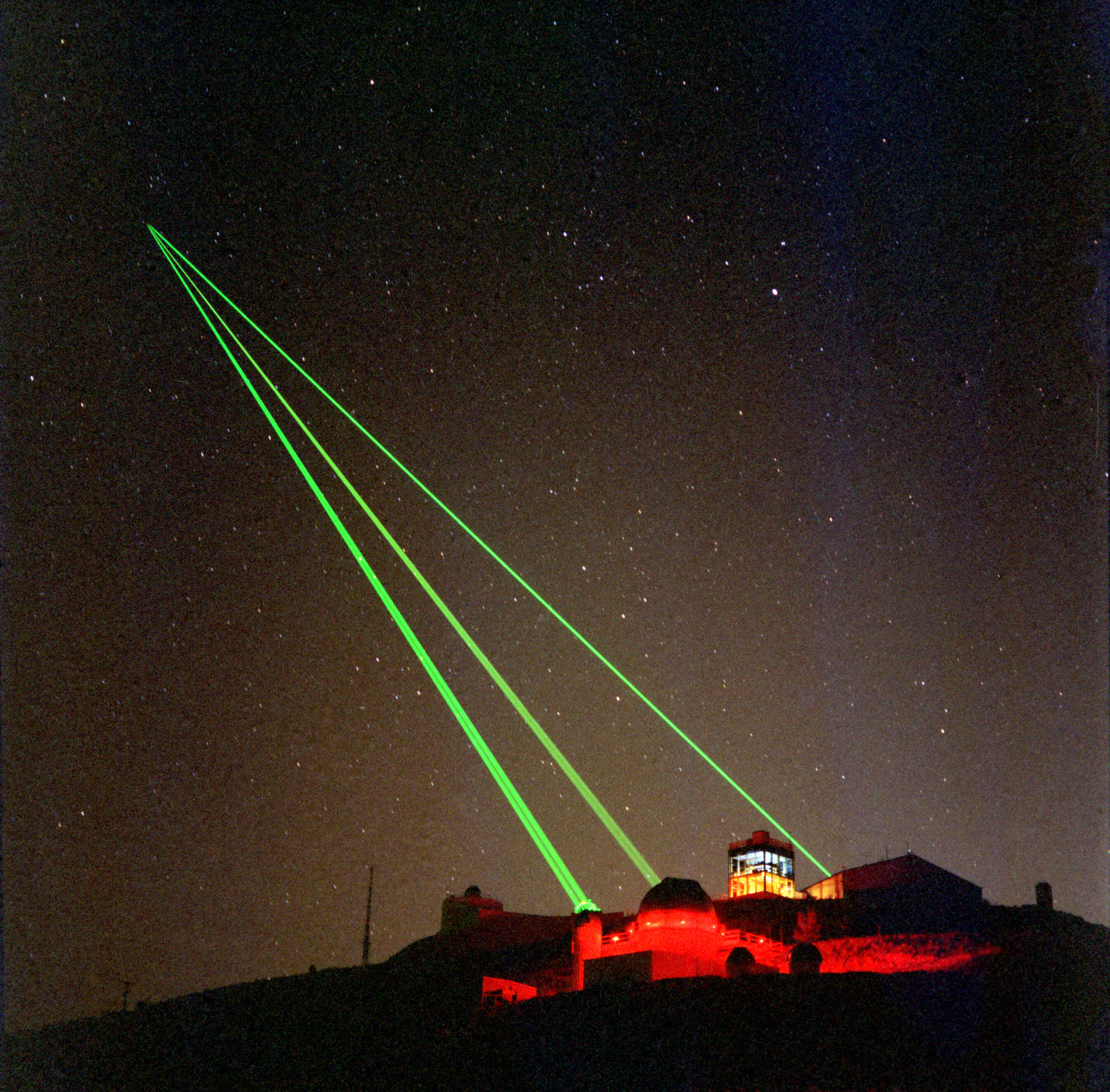
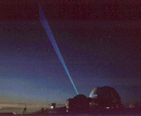
TiPS Laser Ranging Video ..
Starfire Optical Range Firing Lasers, Kirtland AFB The following video clip, taken by the Haleakala, Hawaii Observatory on 21 June 1996, shows TiPS being lazed, as filmed by a hand-held camera. Download TiPS MPEG Video (382 kb) NOTE: To view this video, your computer must have MPEG video viewing software. You can download an MPEG viewer for your particular computer. We have video from most of the TiPS SLR passes. Please email us if you are interested in researching this optical data further.
Air Force Maui Optical Station (AMOS) |
|||||||||||||||||||||||||||||||||||||||||||||||||||||||||||||||||||||||||||||||||||||||||||||||||||||||||||||||||||||||||||||||||||||||||||||||||||||||||||||||||||||||||||||||||||||||||||||||||||||||||||||||||||||||||||||||||||||||||||||||||||||||||||||||||||||||||||||||
|
TiPS Documents ..
|
|||||||||||||||||||||||||||||||||||||||||||||||||||||||||||||||||||||||||||||||||||||||||||||||||||||||||||||||||||||||||||||||||||||||||||||||||||||||||||||||||||||||||||||||||||||||||||||||||||||||||||||||||||||||||||||||||||||||||||||||||||||||||||||||||||||||||||||||
|
Artist's Rendition of the TiPS Separation ..
|
|||||||||||||||||||||||||||||||||||||||||||||||||||||||||||||||||||||||||||||||||||||||||||||||||||||||||||||||||||||||||||||||||||||||||||||||||||||||||||||||||||||||||||||||||||||||||||||||||||||||||||||||||||||||||||||||||||||||||||||||||||||||||||||||||||||||||||||||
|
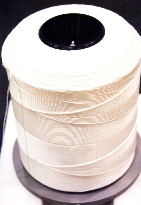
Closeup of TiPS Tether ..
..
|
|||||||||||||||||||||||||||||||||||||||||||||||||||||||||||||||||||||||||||||||||||||||||||||||||||||||||||||||||||||||||||||||||||||||||||||||||||||||||||||||||||||||||||||||||||||||||||||||||||||||||||||||||||||||||||||||||||||||||||||||||||||||||||||||||||||||||||||||
|
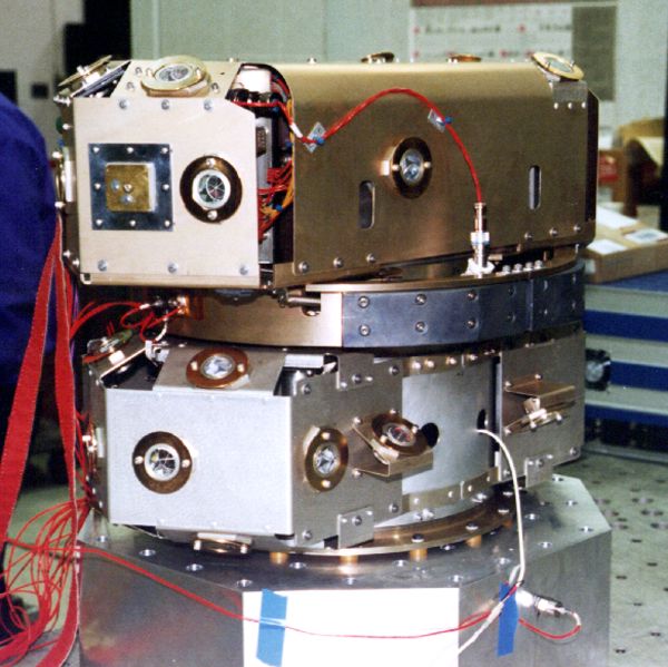
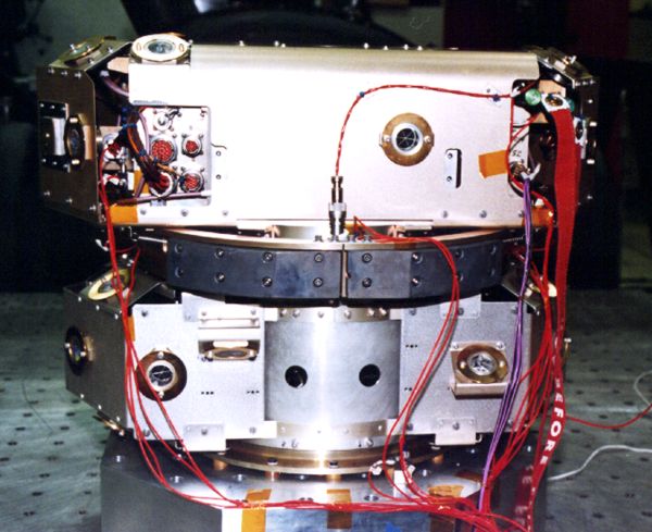
TiPS Vehicle, Summer 1995 ..
..
..
..
Credit: US Navy .. |
|||||||||||||||||||||||||||||||||||||||||||||||||||||||||||||||||||||||||||||||||||||||||||||||||||||||||||||||||||||||||||||||||||||||||||||||||||||||||||||||||||||||||||||||||||||||||||||||||||||||||||||||||||||||||||||||||||||||||||||||||||||||||||||||||||||||||||||||
|
The TiPS Team at NRL, Summer 1995 ..
|
|||||||||||||||||||||||||||||||||||||||||||||||||||||||||||||||||||||||||||||||||||||||||||||||||||||||||||||||||||||||||||||||||||||||||||||||||||||||||||||||||||||||||||||||||||||||||||||||||||||||||||||||||||||||||||||||||||||||||||||||||||||||||||||||||||||||||||||||
|
|
|||||||||||||||||||||||||||||||||||||||||||||||||||||||||||||||||||||||||||||||||||||||||||||||||||||||||||||||||||||||||||||||||||||||||||||||||||||||||||||||||||||||||||||||||||||||||||||||||||||||||||||||||||||||||||||||||||||||||||||||||||||||||||||||||||||||||||||||
|
|
|||||||||||||||||||||||||||||||||||||||||||||||||||||||||||||||||||||||||||||||||||||||||||||||||||||||||||||||||||||||||||||||||||||||||||||||||||||||||||||||||||||||||||||||||||||||||||||||||||||||||||||||||||||||||||||||||||||||||||||||||||||||||||||||||||||||||||||||
| FAIR USE NOTICE: This page contains copyrighted material the use of which has not been specifically authorized by the copyright owner. Pegasus Research Consortium distributes this material without profit to those who have expressed a prior interest in receiving the included information for research and educational purposes. We believe this constitutes a fair use of any such copyrighted material as provided for in 17 U.S.C § 107. If you wish to use copyrighted material from this site for purposes of your own that go beyond fair use, you must obtain permission from the copyright owner. |