|
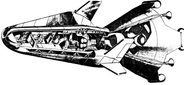
SECTION IV DEVELOPMENT - TEST - PRODUCTION 4.0 INTRODUCTION Implementation of the Lunar Expedition will require a completely integrated program involving the development, test, and production of items based on almost every known technical discipline. These technical disciplines are presently being investigated under a multitude of programs and organisations. The Lunar Expedition program will require these technical efforts to be immediately organised and re-oriented where necessary. This can best be accomplished by preparing a detailed development, test, and production program. When this program is completed each technical area can be evaluated by comparing its present program objectives and its required output to meet the Lunar Expedition program requirements. In the following paragraphs the Lunar Expedition development objectives and technical performance requirements are presented. The scope of the major existing technical programs and the necessary re-orientation is discussed. 4.1 DEVELOPMENT OBJECTIVES 4.1.1 HIGH SPEED RE-ENTRY At the present time high-speed re-entry data in the velocity spectrum from 25,000 ft/sec to 45,000 ft/sec is non-existent. In order to meet the Lunex Re-entry Vehicle development schedule it will be necessary to have high-speed re-entry data during the engineering design program for the manned re-entry vehicle. Thus a compressed and co-ordinated test program for both ground test facilities and flight testing is necessary. Immediate action is necessary to schedule and design the high-speed wind-tunnel test program. This will show the type of information that can only be achieved by means of flight testing. The High-Speed Re-entry flight test program scheduled for the Lunex program is necessary to provide basic data on re-entry as well as to fly specific shapes in the later period of the test program. This selected shape program will be co-ordinated with the Lunex Re-entry Vehicle design effort. In order to accomplish the High-Speed Re-entry flight test program it will be necessary to design and develop a test vehicle. This vehicle must use existing boost systems due to time limitations, but the payload will have to be designed especially for this program since none exists at this time. It is believed that the Atlas booster will prove adequate for these tests, but a decision must await the test payload design. 4.1.2 MANNED LUNAR PAYLOAD The largest single development objective for the Lunex program is to provide a payload capable of transporting men and equipment to the lunar surface and returning them to a selected earth base. This payload would consist of a Lunar Landing Stage, Lunar Launch Stage and a 3-man Lunex Re-entry Vehicle. A typical Manned Lunar Payload is shown in a cut-away view in Figure 4-1. The characteristics and General Arrangement of the Manned Lunar Payload are seen in Figures 4-2 and 4-3. This payload is 52 feet 11 inches long, has the c.g. located 33 feet 8 inches from the nose of the re-entry vehicle and the interface diameter with the Space Launching System is 25 feet. The complete payload weighs 134,000 pounds at escape velocity, and a 20,205 pound Manned Re-entry Vehicle is returned to the earth. The Lunex Re-entry Vehicle must be capable of entering the earth's atmosphere with a velocity of approximately 37,000 ft/sec. At the present time, basic re-entry information for velocities of this magnitude does not exist. Therefore, engineering design effort for this re-entry vehicle must be accomplished concurrently with other major sub-systems developments and integrated with the High-Speed Re-entry test program and the Abort System test and development program. This requires close management control of these programs by the Lunex Program Office. Another major problem facing the re-entry vehicle development program is the life support package. The planned schedule will require the manned life support package to be designed on the basis of earlier primate shots, Mercury shots and the Discoverer series. These programs lead toward a manned capability, but this re-entry vehicle requires the first truly space life support package. The Lunar Landing Stage must be capable of landing the Lunar Launching Stage and the Lunex Re-entry Vehicle on the lunar surface. At the present time this is considered a difficult design problem because little is known about the lunar surface. Actually the best photographic resolution to date is approximately 1/2 mile. Many theories exist on the formation of the moon and therefore, the characteristics of its present surface. When these two factors are considered the only practical design approach is to provide an alighting system capable of landing on an extremely rough surface. An automatic levelling, orientation and launching system is required for system check-out prior to manned flight. Therefore, any assumption that the Manned Lunar Payload can be moved about on the lunar surface or that the payloads might initially transfer fuel on the lunar surface, might be entirely erroneous and jeopardise the complete Lunar Expedition effort. The landing stage will also have to be developed so that it is capable of landing the Cargo Payloads on the lunar surface. The Lunar Launching Stage must be developed with a different philosophy than the previous sub-systems. First, it only operates in the vacuum of space and on the lunar surface. Secondly, it will be required to function after it has been located on the lunar surface for an extended period varying from several days to many months. Therefore, the stage must be developed to launch the re-entry vehicle after being subjected to a better vacuum then available in our best earth laboratory facilities, following possible temperature variations of 400 to 500 degrees, following possible meteorite bombardment and from a less than optimum launch angle. Specifically the stage development must consider propellant boil-off, automatic check-out, self-erection and remote (earth-moon) launching procedures. The Lunar Launching Stage represents the major reliability problem of the system because an abort capability is planned for every phase of the Lunex mission except during launch from the lunar surface. During the early lunar flights an abort capability for this phase is just too expensive payload-wise for the Space Launching System. An abort capability during lunar launch essentially requires a duplicate lunar launching capability because the man must still be returned to the earth by either this system, or a special rescue flight. Therefore, until lunar support facilities are available, a separate system for abort during lunar launch does not seem practical. This creates the requirement to develop an extremely reliable Lunar Launching Stage. 4.1.3 CARGO PAYLOAD The successful support of the Lunar Expedition will require a capability to deliver relatively large Cargo Packages to the lunar surface. These Cargo Packages will be soft landed at the desired lunar sites by the Lunar Landing Stage. Each Cargo Package will weigh approximately 45,000 pounds and will be specifically designed to carry the items desired to support the expedition. Development of the Cargo Payload and the specific packages will depend upon the Lunar Landing Stage design and the receipt of lunar environmental data. The actual design of the Lunar Expedition Facility will only be possible when detailed information on the lunar surface is available. Then, with the facility design information, the required materials, equipment, and procedures can be determined and a payload delivery sequence derived. The required payload delivery sequence is essential before the individual payloads can be designed and developed, but timely development of major items of equipment must proceed as their individual requirements become known. 4.1.4 ABORT SYSTEM The philosophy of abort has been presented in the Program Description section of this document. The development of the abort equipment will require an integrated effort with the re-entry vehicle design and the test program must be conducted concurrently to provide a reliable and safe system for supporting manned operations. It is essential that the re-entry vehicle development be conducted so that the life support capsule can also meet the requirement imposed by the abort system. Additional structural and propulsion items must be developed to provide for abort during the earth ascent phase of the lunar mission. The computing and control equipment on the Manned Lunar Payload must be capable of selecting the desired abort mode of operation and initiating the desired actions at the required time throughout the lunar mission. 4.1.5 SPACE LAUNCHING SYSTEM The Lunar Expedition requires an extensive space launching capability. The development of this capability is a necessary part of the Lunex Program. At present this development is being included under the Space Launching System program. It is designed to support the low altitude test, orbital, circumlunar, and full lunar flights. One of the major problems facing the design and development of the Lunex payloads with reference to the Space Launching System concerns the interface characteristics, trajectory considerations, and earth launch facilities. The present prime interface characteristics for the Manned and Cargo Lunar Payloads are as follows:
4.2 SUBSYSTEM DEVELOPMENT The development of a manned lunar payload and a cargo package requires the development of subsystems and applied research in many technical areas. Studies have established that the advances in performance in these technical areas can be accomplished to meet the overall program schedulers and that no scientific breakthroughs are required. The important point is that items requiring development be identified, that necessary funds be allocated, and that effort be initiated without delay. The following sections discuss major subsystem requirements, present capabilities, and development required. Completed studies conducted by the Air Force and industry have established subsystem requirements in sufficient detail to outline development programs which should be initiated immediately. Present studies will refine these specifications further. 4.2.1 RE-ENTRY VEHICLE 4.2.1.1 The manned re-entry vehicle is a critical item in the
development of the manned payload packages. This vehicle must be capable
of returning from the moon and re-entering the earth's atmosphere at earth
escape velocity (37,000 ft/sec). It must also have the capability of supporting
three men on a 10-day round trip earth-moon mission. This mission would
include boost from earth, coasting in earth orbit, ballistic flight to
the moon, de-boost and landing on the moon's surface, remaining on the
moon for one to five days, launch from the moon's surface, re-entering
the earth's atmosphere and landing at a pre-selected base on the earth.
Structural requirements imposed by inertial and pressure loading during
boost, abort, trajectory correction, landing, re-entry, ground handling,
and wind loading on the launch pad, have been considered in analysing desired
vehicle characteristics. These studies have also included the heating and
its effect on vehicle design as well as the effects of space and lunar
environment including particles and radiation, meteorite penetration, and
hard vacuum. Present design studies have estimated the total re-entry vehicle
height at 20,205 pounds. The weight breakdown is as followers:
4.2.1 2 Present re-entry and recovery techniques are outgrowths of the ballistic missile program utilising ballistic re-entry and parachute recovery. They are not compatible with the velocities associated with re-entry from the moon, with controlled landing, or with manned operations. Present engineering data associated with high speed re-entry is not adequate for vehicle design. 4.2.1.3 A development test program is required to obtain generalised data on re-entry phenomena and to test scale models of selected vehicle configurations so that final selection and design of an optimum vehicle can be made. Concurrently with this test program the projects within the applied research program will be directed so as to carry out the following investigations to provide necessary data for the Lunex Re-entry Vehicle Design. 4.2.1.3.1 AERODYNAMICS (1) Study hypersonic low density aerodynamics including dissociation and ionisation, non-equilibrium flow phenomena, and the influence of radiation non-equilibrium on vehicle aerodynamic and heat transfer characteristics. (2) Initiate an extensive ground based facility program directed at obtaining aerodynamic and heat transfer data up to Mach No. 25 (the maximum useable available capability). These tests would include the G.E. hypersonic shock tunnel in the M = 18 - 25 range; Cornell Aeronautical Laboratory hypersonic shock tunnel M = 12 - 18; Cornell Aeronautical Laboratory heated hydrogen hypersonic shock tunnel at M = 20; AEDC tunnel "B", "C", at M = 8 - 10; AEDC E-1 and E-2, M = 1.5 - 6; AEDC supersonic and subsonic facilities. This effort will be co-ordinated with the Lunex Engineering Design program and the High-Speed Re-entry test program. (3) Correlation of wind tunnel tests in terms of prediction of free-flight vehicle performance characteristics in order to provide correlation between ground test facilities and free-flight vehicles. (4) Complete vehicle static and dynamic stability analysis. (5) Investigate local critical heat transfer problems including those associated with flaps and fins. The use of reaction controls, in order to alleviate critical heating areas, for vehicle stability and control, will be investigated. 4.2.1.3.2 MATERIALS (1) Materials Development (a) Low conductivity plastic material development (2) Uniformly distributed low conductivity. (2) Tailoring conductivity distribution in material in order to obtain high ablation performance at surface and low thermal conductivity in structure bond line. (3) Develop materials with low ablative temperatures. (4) Investigate bonding of materials to hot structure. (b) Develop minimum shape change materials for aerodynamic control surface and leading edge applications. These materials will include pyrolytic graphite, alloys of pyrolytic graphite, and ceramics. (2) Materials Analysis (a) For selected materials above, develop analytical model to predict ablation performance and insulation thickness. (b) Experimentally study material performance under simulated flight environments with the use of high enthalpy arc facilities (h/RT-0 = 700 to 800). (c) Study the influence of space environment on selected materials. This will include the influence of vacuum, ultraviolet radiation, and high energy particles. 4.2.1.3.3 STRUCTURES (1) Primary effort will be in the development of load-bearing radiating structures. For this structure, the following areas will be investigated. (a) Thermal stress analysis and prediction. (b) Dynamic buckling (c) Strain gage applications to high temperatures. (d) Experimental simulation on large scale structures of load temperature distribution, and history. The WADD Structures facility would be the one most appropriate to these tests. 4.1.2.3.4 DYNAMICS (1) Analytical studies in the following areas should be undertaken. (a) Unsteady aerodynamic forces at hypersonic speeds. (b) Aeroelastic changes in structural loading and aerodynamic stability derivatives. (c) Flutter (d) Servoelastic coupling with guidance system. (e) Fatigue due to random loading. (f) Transient dynamic loading. 4.2.1.4 Present projects within the Air Force applied research program will be reviewed and reoriented or effort increased, as appropriate, to provide the necessary data. Projects which can be used for this purpose are listed below: 6173 (U) Study of Controlled Final Deceleration Stages for Recoverable Vehicles. 1315 (U) Bearings and Mechanical Control Systems for Flight Vehicles. 1368 (U) Construction Techniques and Applications of New Materials. 1370 (U) Dynamic Problems in Flight Vehicles. 1395 (U) Flight Vehicle Design. 6146 (U) Flight Vehicle Environmental Control. 1309 (U) Flight Vehicle Environmental Investigation. 6065 (U) Performance and Designed Deployable Aerodynamic Decelerations 4.13 4.2.1.5 In addition to the applied research efforts referred to in Paragraph 4.2.1.4 an intensive study of re-entry vehicle characteristics required for the Lunex mission is being accomplished under project 7990 task 17532. This study will define an optimum vehicle configuration and present the most feasible technical approaches to solving the various re-entry problems. For example, the desirability of ablative and/or radiation techniques for cooling will be determined. 4.2.2 PROPULSION 4.2.2.1 The Manned Lunar Payload requires a booster capable of placing a 134,000 pound package at escape velocity on a selected lunar trajectory. This booster development has been included in the Space Launching System Package Plan and its development will be done for the Lunex program. 4.2.2.2 Propulsion systems for the Manned Lunar Payload which will be developed under this plan are those required for the following operations: Lunar Landing Lunar Launch Trajectory correction Attitude control Abort 4.2.2.3 The Lunar Lending Stage must be capable of soft landing at approximately 20 ft/sec a 50,000 pound payload on the moon. This payload consists of the Lunar Launching Stage and Lunex Re-entry Vehicle. Preliminary design data from studies completed to date show that the manned re-entry vehicle will weigh approximately 20,000 pounds and a launch stage of 30,000 pounds will be required. Similar estimates for the Lunar Landing Stage indicate that it will weigh 85,000 pounds. During lunar landing, if an initial thrust to weight ratio of 0.45 is assumed as consistent with the deceleration desired and time of deboost, an initial retro thrust of 60,000 pounds is required. At final touchdown on the moon, with all delta-v cancelled and assuming essentially all de-boost propellant consumed, approximately 10,000 pounds of thrust is required. Some throttling or gimballing of the engine may be required at the 10,000 pound level to reduce the axial component of thrust. The requirements on the landing engine are for a 60,000 pound engine with a 6 to 1 throttling ratio, or a cluster of four engines of 15,000 pounds thrust and at least one with a throttling range of 1.5 to 1. Assuming a thrust to weight ratio of 1.5 (Moon weight) for the Lunar Launch Stage, a 12,000 pound thrust engine is required for lunar launch. An engine of the LR-115 type will meet these requirements with some development. Minor development will be necessary if the range of throttleability is 20 to 30%. If the range of thrust control is 50% or greater, a more extensive program will be required. 4.2.2.4 In addition to the deboost and launch, it is necessary to provide a trajectory and attitude control propulsion capability. A velocity capability of 300 to 1200 ft/sec will be required for trajectory corrections during midcourse, lunar landing and return. Attitude control will be required during lunar landing and launch, and midcourse, with specific methods to be determined by optimisation studies during vehicle design. There do not appear to be any major development problems to be overcome to provide trajectory correction or attitude control capability. 4.2.2.5 An abort system to provide safe removal of the crew in the event of failure before, or during launch must be developed. A propulsion system with an extremely short reaction time is necessary to insure safe crew removal. 4.2.2.6 Specific engine sizing, throttleability requirements, propellant and oxidizer selection, nozzle type, etc., will be determined upon completion of a preliminary design in which such tradeoff comparisons as range of throttling versus use of verniers will be made and optimized selections made. Development work will be initiated within present projects in the Air Force applied research program to raise the level of technology in areas such as throttleability. Projects which can be utilized for this purpose are: 3085 (U) Liquid Rocket Engine Technology 3148 (U) Development of Liquid and Solid Rocket Propellants 6753 (U) Rocket Propulsion Subsystems 6950 (U) Propulsion Attitude Testing 4.2.3 LIFE SUPPORT 4.2.3.1 The life support package for the manned Lunar Payload will be required to function for a minimum of 10 days. This is based on the premise that a one-way trip to the moon will require 2 1/2 days, and the stay on the lunar surface will be on the order of 5 days. The life support systems must be capable of supporting three men during high acceleration boost, approximately 2 1/2 days of weightlessness, one to five days of 1/6 earth weight, 2 1/2 days of weightlessness, re-entry deceleration and return to full earth gravity. At the same time it must provide a shirtsleeve cabin environment under the space and lunar environments, including extreme temperature gradients, absence of oxygen, radiation, etc. 4.2.3.2 Studies of the life support system weight requirements indicate that the life support package can be provided within the weight allocation for the 20,000 pound Lunex Re-entry Vehicle. The life support system weight analysis was based on physiological experiments under simulated apace flight conditions such as confinement, special diets, reduced pressure, etc. At the present time approximately 65 to 70 percent of the knowledge required to design the three man package is available. However, to obtain the additional data experimental laboratory and flight testing is required. Most information is presently obtained by piggyback testing aboard experimental vehicles, but to support the Lunex program and to meet the desired schedules the BOSS primate program must be initiated and adequately supported. 4.2.3.3 Most of the data available today consists of physiological support (nutrition, breathing oxygen, pressure suits, and restraints for limited periods), but there is a lack of knowledge on prolonged weightlessness and the biological effects of exposure to prolonged space radiation. The BOSS program initially will support a chimpanzee for periods up to 15 days and has been programmed to provide a life support package of sufficient size and sophistication to support a man. Thus, with the BOSS program the data will become available so that the Lunex program can design and construct the life support package as required for April 1965. 4.2.3.4 Throughout this development all life support knowledge and techniques will be fully exploited. Techniques learned in the work with the Discoverer package were utilised in building the Mercury package. In turn, experience and knowledge gained from Mercury is being fully exploited in the development of the present BOSS package . 4.2.3.5 The life support program (BOSS) is vital to meet the objectives of the Lunex program. However, other AFSC programs must be considered for possible application to Lunex and the following are now being evaluated: 6373 (V) Aerospace Life Support 7930 (U) Bio-Astronautlcs 4.18 4.2.4 FLIGHT VEHICLE POWER 4.2.4.1 Electrical power will be required to operate the Lunex Re-entry Vehicle subsystems such as life support, navigation and guidance, instrumentation, and communications. The power requirement for there subsystems, has been analysed and determined to he approximately 3 kW average during a ten-day manned trip to the moon and return. Peak power requirement will be approximately 6 kW. 4.2.4.2 Solar, nuclear, and chemical powered systems were evaluated against these requirements. While all of these systems may be capable of meeting these requirements the chemically powered systems have been selected for early adaptation into the program. Specifically, fuel cells and turbines, or positive displacement engines appear to offer the moat advantageous solution. The final selection will be made during the final re-entry vehicle design when a detailed analysis of the trade-off between various available systems considering relative weight, efficiency, reliability, and growth potential is available. The optimum system may be a combination of fuel cells and chemical dynamic systems with one system specifically designed to supply peak demand. With this approach the system to provide peak load capacity, will also provide backup power in the case of equipment malfunction during a large part of the mission. A battery supply may be used to furnish emergency power required for crew safety during critical periods in the flight. 4.2.4.3 Present level of technology is such that a satisfactory flight vehicle power system will be available when required for the Lunex mission. Additional development effort should be initiated in certain specific areas, such as a reliability evaluation program for fuel cells and an investigation of the problems of operating chemical dynamic systems in the zero G environment. Close co-ordination must also be maintained with the manager of project 3145 (U) Energy Conversion, to insure the availability of the required secondary power sources. 4.2.5 GUIDANCE AND CONTROL SYSTEM 4.2.5.1 A study of the guidance and control requirement for the lunar vehicle indicates that the mission can be accomplished by reasonable extensions of present state-of-the-art equipment. The complete lunar vehicle guidance package should be capable of furnishing guidance and control during the following phases of the lunar mission. Ascent and Injection Outbound Mid-course Lunar Landing Lunar Ascent Inbound Mid-course Earth Re-entry Earth Landing Present state-of-the-art equipment is capable of handling portions of the guidance and control problem associated with the above phases of flight. However, in order to obtain a complete guidance and control system, it is felt that development of the following items should be undertaken. 4.2.5.2 INERTIAL PLATFORM Guidance requirements for both the manned and unmanned vehicles can be met with the use of guidance concepts based on the use of inertial and corrected inertial data in a combination of explicit and perturbation computations of present and predicted trajectories. Consequently, an inertial platform configuration suited to the space environment is needed. This platform should be light in weight, highly reliable, and capable of maintaining a space-fixed reference over a long interval of time. Present gyroscopic devices and accelerometers are neither accurate nor reliable enough to accomplish the space mission. An inertial platform which holds great promise for use in lunar missions is one utilising electrically suspended gyros in conjunction with advanced accelerometers capable of operating in a space environment. Present electrically suspended gyros are capable of operating with a drift rate of .0005 deg/hr/g and it is anticipated that by 1966, a drift rate of .0001 deg/hr/g will be attainable. Also, no difficulties are foreseen in maintaining suspension of the rotating member in an acceleration field of 15 G's with 30 g's being possible. Development of a small inertial platform utilising electrically suspended gyros will be required for the lunar mission. 4.2.5.3 STAR TRACKER In order to increase the reliability and the accuracy of the inertial platform, a compact star tracker for use with the platform during the outbound and inbound mid-course phases of the lunar flight is desired. Also, the star tracker should be capable of operating in a lunar environment so that it can be used for stellar alignment during the lunar launch portion of the mission. The accuracy of present solid state star trackers is approximately 10 seconds of arc and their weight is approximately 15 pounds. However, these trackers are untested in a space environment and must be developed for the lunar mission and for use with the small inertial platform. In particular, the star tracker must be capable of furnishing accurate stellar alignment information to the inertial platform during the lunar ascent portion of the mission. If it is possible to develop a controllable thrust engine in time to meet the launch schedule, the boost and injection guidance problem for the lunar ascent will be simplified as it will be possible to time-control a predetermined velocity path. This development could possibly reduce the accuracy requirement of the star tracker. 4.2.5.4 LONG BASELINE RADIO NAVIGATION Since manned as well as unmanned flights are planned for the lunar mission, it is necessary to have a navigation system to back-up the inertial system and to increase the over-all accuracy of the guidance and control techniques. Long baseline radio/radar tracking and guidance techniques offer great possibilities for tracking and guiding vehicles in cislunar apace. Present studies show that there are a number of problems yet to be solved to give the long baseline radio navigation the desired accuracy. Among these problems are 1) the accuracy with which co-ordinates can be determined for each tracking station, 2) the accuracy with which corrections can be made for tropospheric and ionospheric propagation effects on the system measurements, and 3) the accuracy with which "clocks" can be synchronised at the several stations. Reasonable extensions of the state-of-the-art should be able to overcame these problems however, and it is felt that the development of a long baseline radio navigation system will be necessary for the lunar mission. 4.2.5.5 DOPPLER RADAR Anticipation that radio beacons will be in place on the lunar surface has somewhat simplified the lunar landing phase of the mission. The use of mid-course guidance will enable the vehicle to approach the moon within line-of-sight of at least one of the radio beacons, and the beacon can be utilised for the approach phase of the lunar landing. However, for final vertical velocity measurement, a sensing technique particularly sensitive to small velocity changes is required. A small CW Doppler radar is ideally suited for this requirement. Therefore development of a small, reliable Doppler radar which can operate in the lunar environment is needed. In order to decrease the power requirement for the radar it should not be required to operate at a range of over 300 miles. 4.2.5.6 RE-ENTRY GUIDANCE Major emphasis must be placed on the guidance requirements for the re-entry phase of the lunar mission. Position, velocity, and attitude can be measured by the inertial system, however, other measurements initially required will be temperature, temperature rate, structural loading and air density. Extensive further study is needed to define these measurements with any accuracy. Early earth return equipment should furnish the data necessary to develop the required re-entry guidance package for the lunar mission. 4.2.5.7 ADAPTIVE AUTOPILOT The control of the re-entry vehicle mill require an adaptive autopilot due to the wide variation in surface effectiveness. Adaptive autopilots such as used in the X-15 are available, but extensive development is needed to ready them for use in the lunar mission. 4.2.5.8 The following projects or specific tasks within these projects can be utilised to provide the development required for the Lunex program. 4144 (U) Guidance and Sensing Techniques for Advanced Vehicles 40165 (U) Data Conversion Techniques 50845 (U) Guidance Utilising Stable Timing Oscillators 50899 (U) Molecular Amplification Techniques 4427 (U) Self-Contained Electromagnetic Techniques for Space Navigation 4431 (U) Inertial System Components 44169-II (U) Space Adapted Celestial Tracking System 44169-III (U) Multi-Headed Solid State Celestial Tracker 44169-IV (U) Solid State Celestial Body Sensors 5201 (U) Inertial Systems Technique 5215 (U) Military Lunar Vehicle Guidance 50820 (U) Military Lunar Vehicle Guidance Systems 58821 (U) Military Lunar Vehicle Terminal Guidance 4.2.6 COMPUTER 4.2.6.1 The United States has the ability to provide a suitable computer facility at the present time to support the Lunex mission. As the milestones in the program are realised and requirements become more complex, the computer capability will improve to meet these more stringent requirements. Detailed studies on the specific needs of the missions, time-phased, will be conducted to determine trade-offs among possible techniques to insure that machine sophistication does not became an end unto itself. The following guidelines providing adequate flexibility, have been followed in arriving at the required development recommendations: a. Manned vehicles will require extensive data reduction to give an operator real-time displays of the conditions around him and solutions to problems such as, velocity and attitude corrections, etc. b. Sensor control (aiming and sampling rate) and data processing will be accomplished on the vehicle either on ground command, or by operator direction. c. Mid-course and terminal guidance requirements will make severe demands upon vehicle-borne computational systems. d. Radiation hazards and effects which are unknown at present could influence the technology that will be utilised for lunar missions. e. Emergency procedures must be available in the event that the operators became incapacitated and incapable of returning to earth at any time during the mission. 4.2.6.2 The computer capability can be expanded in two basic ways by improved hardware, or new concepts. Examples of new approaches which will be reviewed prior to selection of the final vehicle design are the following: a. Standardised computer functions incorporated into modules so that they can be used to "build" their capability for each mission required. Such a concept would allow a vehicle designer to fabricate a computational facility without resorting to extensive redesign and/or re-packaging. The modularised concept noted above is particularly adapted to unmanned missions. b. For a manned mission two fixed programs could be permanently placed in storage; these would be an overall command, or executive routine to direct the sequences of operation, and the other could be an emergency return-to-earth routine that could be actuated by the master control. Thus a 5-pound tape unit would replace a larger core memory and provide a higher degree of flexibility. The principal advantage in this system is that the computer is general-purpose in design and therefore useable on a large variety of missions and unnecessary capabilities will not be carried on a particular mission. c. An optimised hybrid of analogue and digital devices combined to use the better features of each, i.e., speed of problem solution from the analogue and precision, flexibility, and data reduction from the digital. 4.2.6.3 Substantial improvements in computer capability, developments, reliability, volume, weight, and power consumption will be available for the Lunex program by effort expended in the following areas: a. Core-rope memories to be used in fixed memory applications. b. Functional molecular blocks. By 1963, the date of earth orbit, it is expected that more than 80% of all computer functions can be performed by this method. Advantages are numerous: high memory densities, extremely small size, small weight and power consumption. c. Self-healing, or adaptive programming techniques as a means for back-up on component reliability. d. Electroluminescent-photoconductive memory devices should be considered for their radiation and magnetic invulnerability. In this regard, pneumatic bistable elements should be considered for the same reason. e. Photochromic storage devices have advantages in high storage densities, 1 billion bits/cubic inch. Certain applications, such as semi-permanent storage, could benefit from this feature. 4.2.6.4 The following projects in the Applied Research Area will be utilised to obtain improvement in computer technology: 3176 (U) Space Borne Computation & Control Techniques 4421 (U) Digital Computation Methods & Techniques Continued at Lunex -
Chapter 3
Last update 12 March 2001. Contact Mark Wade with any corrections or comments. Conditions for use of drawings, pictures, or other materials from this site.. © Mark Wade, 2001 astronautix.com |