|
Electrodynamic Tether Photos |
||||||||||
|
||||||||||
|
.
|
||||||||||
|
||||||||||
|
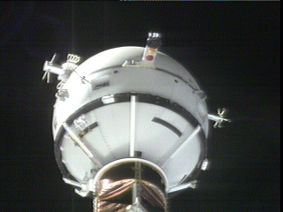
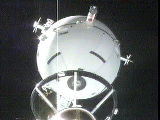
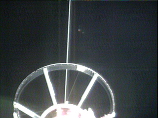
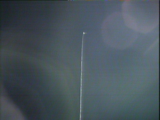
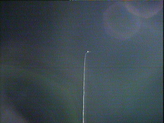
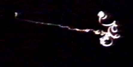
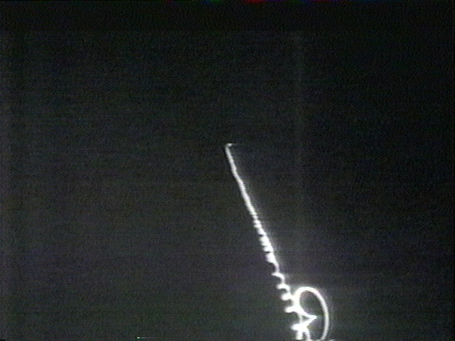
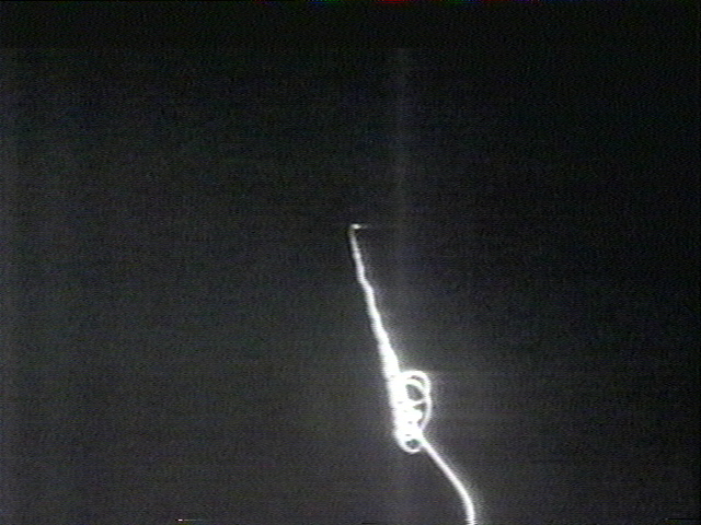
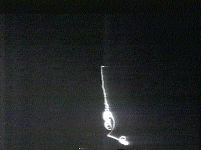
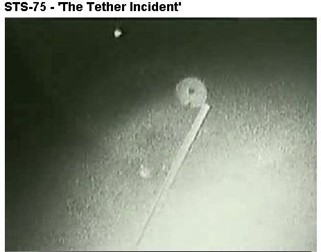
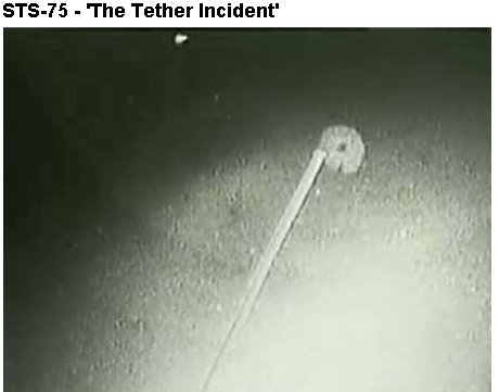
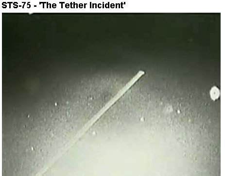
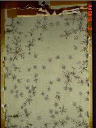
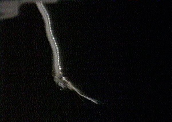
The following three images are those displayed for the public showing the white specks that appearall around the tether after it has broken free. NASA calls these "dust and debris" particles, though Mission control in the audio portion of the videos state that they see a "lot of stuff swimming around" and that the tether is wider than expected.
Video Clip
Comments:
Tethered
Satellite System (TSS-1R)
|
||||||||||
|
NASA/TP—2003-21228
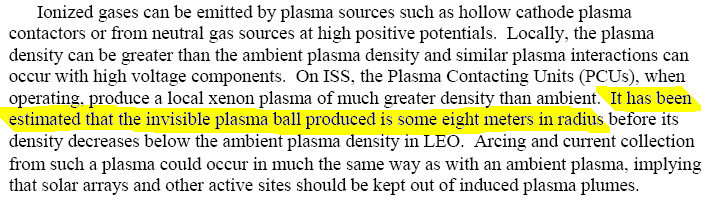
Below are a few keynote excerpts from the PDF file. The entire 367 page document is available below for those with technically savy who want to read the entire paper... Excerpt 1: In the case of the TSS-1R tether, its 20 km length produced a maximum
of about 3500 V potential between its most positive and negative ends,
since it wasn?t oriented perfectly perpendicular to the velocity vector
and the Earth?s magnetic field. A satellite at its upper end collected
electrons, and an electron gun at the lower end emitted electrons to complete
the circuit. When the electron gun was not in operation, a large resistance
prevented the Shuttle from being biased thousands of volts negative of
its surrounding plasma. However, there remained a large voltage between
the tether lower end and the Shuttle orbiter. This
enormous bias eventually led to a continuous arc on the tether (see
The Continuous Arc, section 4.2.3.1 below), which broke, freeing the satellite
and ending the experiment. During the arc, the satellite collected over
1 Amp of electron current to keep the arc going. Probe theory (Cohen et
al, 19870010625 N) is usually used to calculate the total current collected
by a wire with distributed potentials. However, before the break, TSS-1R
demonstrated that a satellite at a high positive potential could collect
an anomalously large electron current. See Zhang, et al (20000110580),
Stone and Raitt (19990084046 and 20000025437), and Stone, et al (19980202347)
|
||||||||||
| Excerpt 2:
Sustained arcs (continuous arcs) - These are the events that have
been attributed with the destruction of on-orbit solar arrays. Generally,
the process begins with a fast transient (a so-called trigger arc). Under
some conditions, the transient develops into an arc that is fed directly
by the entire array, effectively becoming a short-circuit. Such events
invariably involve large quantities of energy and can be severely damaging
to cells, interconnects or power traces.
|
||||||||||
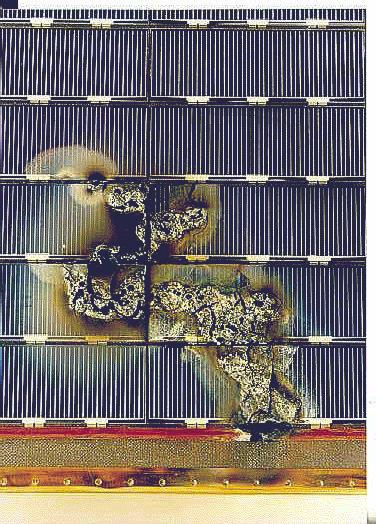
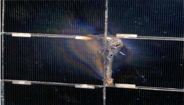
| Excerpt 3:
When the structure or array capacitance electrically connected to
the arc site is sufficiently large, the initial transient arcs themselves
can be large enough to produce significant damage. In Figure 9, we see
an anodized aluminum plate that has undergone repeated arcing in the laboratory
with the ISS structure capacitance attached. Its thermal properties have
been completely destroyed, along with most of the insulating surface layer
of aluminum oxide.
|
||||||||||
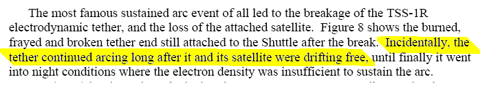
| Excerpt 4:
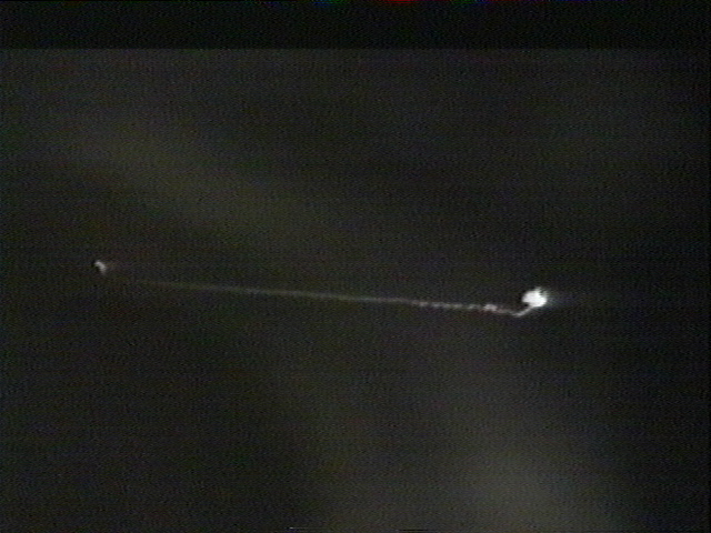
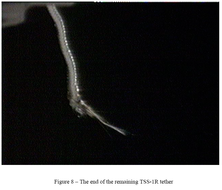
The most famous sustained arc event of all led to the breakage of
the TSS-1R electrodynamic tether, and the loss of the attached satellite.
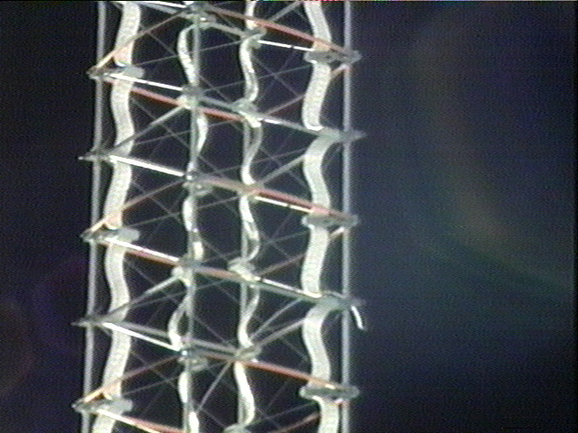
The image below shows the burned, frayed and broken tether end still attached
to the Shuttle after the break. Incidentally,
the tether continued arcing long after it and its satellite were drifting
free, until finally it went into night conditions where the electron density
was insufficient to sustain the arc. Noel Sargent (2002)
has investigated whether the TSS-1R arc was seen to disrupt Shuttle communications.
Although he has found no record of disturbed communications during the
event, for most of the time the arc was shielded by metallic structures
from the communications antennas, and when the tether broke, the arc was
many meters from the receiving antennas. It remains to be seen whether
sustained arcs produce radio noise severe enough to be a communications
problem.
Comments: This is official confirmation that the tether continued to produce
plasma energy long after it broke free, accounting for the "fluorescent
bulb" glowing effect viewed after. We believe this concentrated collection
of plasma energy is what attracted the "swarm" of "critters" to a "feeding
frenzy"
To get the full PDF file you can download LEO_Charging_Guidelines_v1.3.1.zip
Using a hand-held camera system with image intensifiers and special filters, the TOP investigation will provide visual data that may allow scientists to answer a variety of questions concerning tether dynamics and optical effects generated by TSS-1R. In particular, this experiment will examine the high-voltage plasma sheath surrounding the satellite... In one mode of operation, the current developed in the Tethered Satellite System is closed by using electron accelerators to return electrons to the plasma surrounding the orbiter. The interaction between these electron beams and the plasma is not well understood... Associate Investigator: Stephen Mende, Lockheed Martin |
||||||||||
|
...
|
||||||||||
| FAIR USE NOTICE: This page contains copyrighted material the use of which has not been specifically authorized by the copyright owner. Pegasus Research Consortium distributes this material without profit to those who have expressed a prior interest in receiving the included information for research and educational purposes. We believe this constitutes a fair use of any such copyrighted material as provided for in 17 U.S.C § 107. If you wish to use copyrighted material from this site for purposes of your own that go beyond fair use, you must obtain permission from the copyright owner. | ||||||||||
|
Critters ~ Critters 01 ~ Critters 02 ~ Critters 03 |